The data in a database could easily be designed using only one table that contains all data. The main disadvantage of such a database design is its high redundancy of data. For example, if your database contains data concerning employees and their projects (assuming each employee works at the same time on one or more projects, and each project engages one or more employees), the data stored in a single table contains many columns and rows. The main disadvantage of such a table is that data is difficult to keep consistent because of its redundancy.
The entity-relationship (ER) model is used to design relational databases by removing all existing redundancy in the data. The basic object of the ER model is an entity—that is, a real-world object. Each entity has several attributes, which are properties of the entity and therefore describe it. Based on its type, an attribute can be:
- Atomic (or single valued) An atomic attribute is always represented by a single value for a particular entity. For example, a person’s marital status is always an atomic attribute. Most attributes are atomic attributes.
- Multivalued A multivalued attribute may have one or more values for a particular entity. For example, Location as the attribute of an entity called ENTERPRISE is multivalued, because each enterprise can have one or more locations.
- Composite Composite attributes are not atomic because they are assembled using some other atomic attributes. A typical example of a composite attribute is a person’s address, which is composed of atomic attributes, such as City, Zip, and Street.
The entity PERSON in Example 1 below has several atomic attributes, one composite attribute, Address, and a multivalued attribute, College_degree.
EXAMPLE 1:
PERSON (Personal_no, F_name, L_name, Address(City,Zip,Street),{College_degree})
Each entity has one or more key attributes that are attributes (or a combination of two or more attributes) whose values are unique for each particular entity. In Example 1, the attribute Personal_no is the key attribute of the entity PERSON.
Besides entity and attribute, relationship is another basic concept of the ER model. A relationship exists when an entity refers to one (or more) other entities. The number of participating entities defines the degree of a relationship. For example, the relationship works_on between entities EMPLOYEE and PROJECT has degree two.
Every existing relationship between two entities must be one of the following three types: 1:1, 1:N, or M:N. (This property of a relationship is also called cardinality ratio.) For example, the relationship between the entities DEPARTMENT and EMPLOYEE is 1:N, because each employee belongs to exactly one department, which itself has one or more employees. Also, the relationship between the entities PROJECT and EMPLOYEE is M:N, because each project engages one or more employees and each employee works at the same time on one or more projects.
A relationship can also have its own attributes. Figure 1 shows an example of an ER diagram. (The ER diagram is the graphical notation used to describe the ER model.)
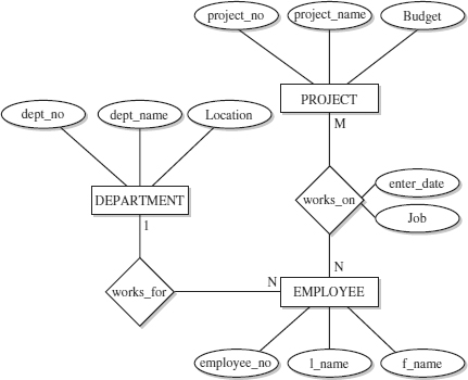
Figure 1. Example of an ER Diagram
Using this notation, entities are modeled using rectangular boxes, with the entity name written inside the box. Attributes are shown in ovals, and each attribute is attached to a particular entity (or relationship) using a straight line. Finally, relationships are modeled using diamonds, and entities participating in the relationship are attached to it using straight lines. The cardinality ratio of each entity is written on the corresponding line.
Leave a Reply