To understand Exadata’s performance, it’s helpful to look at traditional enterprise storage. Traditional storage is dominated by large storage area networks (SANs) and network attached storage (NAS) devices. These storage architectures help to share and manage storage among multiple client devices, but their main building blocks are large banks of rotating hard drives and solid-state storage devices. These drives use the same underlying technology as storage in personal computers, although they’re built to handle the higher speeds and usage volumes that enterprise workloads demand.
These disks are connected to storage heads, which are themselves computers that handle the “smarts” of the storage. They spread data across multiple disks and duplicate data across disks to handle the failure of individual drives using various types of RAID (redundant array of independent disk) storage technology. Storage heads process data access requests from client devices (such as database servers), pass them on to individual drives, and assemble the result, passing it back to the client device. Storage heads are, therefore, able to present large arrays of drives as large logical drives, hiding the complexity from client devices.
As storage demands increase, it’s relatively simple to add more disk drives. But because the storage heads handle requests for multiple disk drives, it’s much more difficult to add processing capacity. Similarly, the links between storage heads and database servers need upgrading as data volumes increase.
Exadata is architected very differently from traditional storage: Because there is no central storage head, system capacity can be expanded by simply adding more database and storage servers. Because it’s a switched network configuration, the InfiniBand network increases aggregate network capacity as servers are added.
Exadata Storage Concepts
Exadata storage servers each contain a set of disk drives that form permanent storage. The actual disk storage is organized into a hierarchy of disk types, as described in Figure 1.

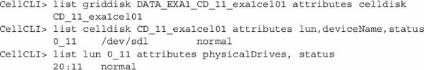
Each grid disk corresponds to an ASM disk on the database server. The PATH column in V$ASM_DISK lists the storage server IP address and grid disk name. This example lists paths of the grid disks in diskgroup DATA_EXA1:

On storage servers, disk objects can be viewed and manipulated through CELLCLI commands or with Oracle Enterprise Manager.
Each of the CELLCLI listing commands has similar syntax:
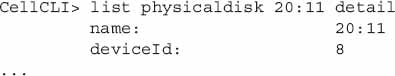
The DETAIL keyword returns a full list of object attributes and values:
Additionally, grid disks can take advantage of hot and cold disk placement to take advantage of a unique property of rotating magnetic disks at constant angular velocity: Outer tracks are physically bigger and can store more data, allowing higher transfer volumes per disk rotation than inner tracks. This type of layout is commonly used to place database contents on faster outer tracks, and the less performance-intensive fast recovery area on slower outer tracks. And because frequently used database data is spread over a smaller part of the disk, less time is wasted moving disk heads between tracks.
Hot/cold placement is simply configured by creating the “hot” grid disks first. They will be automatically placed on the fastest part of the disk, and remaining diskgroups on progressively slower parts.
Leave a Reply